Tuesday, October 27, 2009

Spears for Vinland

One of my current (paid!) jobs is to make a number of pieces for the Encampment program at L'Anse aux Meadows NHSC. This year's additions are a set of spears and shields - five of each. There are also a group of arrows being made up by Mike Kleinknecht . (Forging the arrow heads was detailed on an earlier posts : ONE / TWO / THREE.)

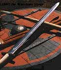
The spears are made in two basic patterns, forged from mild steel. There are two of a shorter javelin head, about 6 inches in blade length. The other pair are longer, slashing heads, these closer to 9 inches in blade. All are full socket type. The last of the set (seen at extreme right) is a more leaf shaped blade. This I forged from antique wrought iron - the material that is more likely to have been used for the originals. From a distance there is no difference, but close examination shows the distinctive linear grain in the actual iron.
On all the spears, the sockets were forged separately from standard schedule 40 mild steel pipe. The heads were forged down to a short stubb tang. That tang was forced into the hot cone of the socket, which when cool was MIG welded and ground smooth. That last is 'cheating' in terms of historic method, but in practical terms, you can't tell the difference in appearance between the MIG and a proper forge weld. (And yes - I have made these up with forge welds in the past.)
I deliberately chose NOT to polish the blade surfaces down to remove all the forge pitting. This shows primarily along the spines of each blade. The logic here was to preserve as much as the original thickness of the material as possible. Each of the blades was forged from 1/4 x 2 inch flat stock.
The shafts were purchased from a London Ontario supplier, Relics. They sell a very nice quality, straight grained ash spear shaft, for about $45 CDN. (Watch out on the shipping cost - I had the order picked up)

(Additional comment)
Jason asked:
... How are the heads fastened to the shafts? Just shaped and forced on hot? Riveted?
The heads are basically friction fit. The end of each shaft was tapered with a draw knife to the basic shape. I then fit the sockets down, rotating them as I did so. This would scrape some of the internal fire scale on to the wood, marking the high spots. These were then reduced with a course file. Repeat until pretty much the whole taper is being marked (indicating a tight fit). Normally fitting the socket back on to the shaft, then tapping the base of the shaft is enough to firmly mount the spear head.
As these are going into a living history situation (where I know from past experience a certain amount of abuse is almost certain) I did cheat at this point. Each socket got a liberal coating of epoxy before I did the final setting of the head. After this was hard, any excess was trimmed with a knife. The epoxy is this invisible, but ensures the heads will not work loose.

(Additional comment 2)

polymarkos asked

...how did you make nice conic shapes out of the black pipe for the sockets?


Carefully!
The trick to getting long tapered shapes out of pipe is to hammer quickly and using gentle strokes - with a lighter hammer. I use a 800 gm / 1.5 lb weight as my primary forging hammer. Working down into a conical bottom hardie tool also helps speed the work. There is a short photo description of forging long tapers to points out of pipe on an earlier blog entry : Forging Rush Tips - which also includes a video clip of the process.

Sunday, October 25, 2009

Clay at L'Anse aux Meadows?

This is a response to a comment by one of the regular voices on the Early Iron Group discussion.

Do you make a difference between loam and clay?
We always use loam mixed with sand and other things (when needed).
I am sure that the inside of the furnace wall participates at the proces. I dig out the loam as close as possible to the ore bank.

Loam has very less lutum and clay minerals but much iron combinations.
If you mix it with (lots of) sand it dries very quick and you can even start firing it while it is still wet.
I am curious about the situation of loam and ore near the excavation of that oven in LaM.

Thijs.


At the physical site of L'Anse aux Meadows itself there is not any clay material present. On the actual Viking Age occupation area, the location is a sea shore, with a narrow bank that rises up out of the shallow water. The bank is maybe 30 metres wide. This bank then falls away into a bog, so imagine a thin crescent shape that runs along the sea. So what you have is a combination of fine stones and sand at the water line (a fine gravel). The core of the bank (especially around the furnace hut where the smelter is) is mainly sand. This is topped with a layer of compressed organic material - peat. The bog side is of course peat as well.
Looking roughly north, out over the Marine Terrace at L'Anse aux Meadows NHSC.
The Norse occupation area extends bit more to the right than is seen in this image. The white area with benches seen to the right centre is roughly were the charcoal pit was found, just below it, dug into the stream bank, was the 'Furnace Hut' and its iron smelter.

There is a clay bank in the area. I personally have not seen this, so can't tell you exactly how close it is, or exactly what consistency or kind of deposit it is. A couple of the local people told me about it. One of the staff members at Norstead (an attraction in the area) had been digging the stuff out and building and firing simple hand built pots out of this clay. It looked like a pretty clean low firing grey clay. Most certainly this clay deposit will be some form of water deposited material, my guess is that it would be along one of the many streams in that region. The Norse would certainly have had to have hand carried the stuff a good distance!

From what I saw at Ribe (with Michael Nissen) and Heltborg (with Jens Olesen) the situation in Denmark is quite different. What I observed at both those locations is quite deep underlaying clay and sand layers making up the whole ground. This base material had organic material mixed with it as the top layer, often pretty thin in places. So when you stuck a shovel in, you pretty much got some combination of clay, sand and bits of vegetation. For the Heltborg symposium in 2008, Jens had a pile of clay that they had just used a front end loader to scoop out of the side of a hill. That stuff was almost pure clay, we actually had to add extra sand to it - just as it came from the earth. I was quite amazed! (Denmark, the land of iron riches.)

So I think what you are calling loam is a mixture of materials that does not naturally occur at LAM (and most certainly not around here where I live in Wareham - some 3000 km away!)

We have been adding straw (typically wheat stocks that are gathered up into bales after the crop is harvested), chopped into roughly 5 - 8 cm lengths. Our typical mix is roughly 50 % dry powered potters clay, mixed with an equal volume of the straw. Add enough water to let you manipulate the stuff by hand. Normally we only add sand to balance the water content (like if we use too much water by mistake - its hardly exact). My experiences absolutely agree with yours, the inclusion of vegetation in the form of plant stems both helps to hold the constructed walls together against cracking, but also allows any steam to vent into the hollow stems (or out through the channels) to reduce cracking as well. We also have repeatedly gone straight from building wet cobb mix walls straight to the pre-heat with split wood with no real problems.

Working with straight clay is another matter. Twice we have used boxes of prepared potters clay, which comes pre-mixed as large blocks, soft enough to hand work, maybe 20 x 15 x 25 cm. (Smelts in October 07 and the last one on October 11 09) We cut these with a dry wall saw into thick slabs, about 5 cm thick (so 'brick' shapes, about 15 x 5 x 25) These were stacked, on end, a rough octagon shape, then smoothed over at the edges. As there is nothing to help let the steam escape from inside the 5 cm thick mass, there were plenty of pops, cracks - and flying clay pieces, as the pre heat was underway. Pieces as large as a golf ball flew as far as 5 metres a couple of times! Too exciting. As I mentioned in the last short report , having the clay construction surrounded by stones and packed with sand / ash mix, both held the structure together and helped to keep (most) of the combustion gases inside the smelter.

We have had excellent results with the clay and chopped straw cobb construction. Individual furnaces have been re-used as many as five times with only minor repairs (around the tuyere area). The structures stand up to Ontario winters, by just putting a cover over the top to keep the snow out. Once the walls have gone through a smelt sequence, they pretty much sinter into a rough ceramic and are pretty durable. Built at our normal 7 - 8 cm thickness, they are strong enough to be self supporting. To construct a furnace at 25 cm interior diameter and roughly 60 cm tall requires about two and half 20 kg bags of dry clay. The cost for that around here is about $30 CDN.

Thursday, October 22, 2009

A Furnace at Vinland - Construction Possibilities

The terminology used to describe historic direct iron smelting furnaces is not uniform, although some influential authors (primarily Pleiner) have attempted to establish a descriptive system. Mostly these are based on slag remains and slag management systems. (Understandably, as it is glassy slag which is often all that remains to examine through archaeology.) In this summary the stress is in the construction of the upper portions of the furnace. The furnace used by the Norse at Vinland, circa 1000 AD, is being presumed to have been constructed with no large tap arch, and to have used the top extraction method.
There are four basic possibilities for how the iron smelting furnace at 'Leif's Houses' (L'Anse aux Meadows) might have been constructed:

1) A clay cylinder that is free standing
2) A (thin?) clay cylinder inside a ring of supporting stones
3) A stone slab box with clay only sealing the corners
4) A series of smaller stones mortared together with loose clay into a cylinder

The Dark Ages Re-creation Company team has built and effectively operated furnaces using all of the first three possible construction methods. In this report, I will offer up samples of historic furnaces constructed using the various methods. (Those images are from Pleiner's 'Iron in Archaeology' or were kindly provided to me by Dr Birgitta Wallace.) One important fact - all the historic examples appear to be from 'industrial' level iron processing sites. Those furnaces are larger (some as large as 60 cm ID), and intended to produce larger blooms per firing than our normal test furnaces. They are also very heavily constructed, clearly intended for multiple firing sequences. Both of these features are to be expected in a location specifically built for full scale iron production. One important consideration is to remember the furnace built at Vinland was only intended for a single use, and is made using a lighter construction to reflect this.
LAM 2 - October 2009. Interior of furnace (tuyere at middle left) near the end of pre-heat.
Lighter coloured flaws on the inner surface are marks where damp clay has spalled off during heating.

The clay debris recovered at LAM do do not indicate any organic materials have been added to the clay used in construction. Our own experience is that without the inclusion of straw (cobb) any clay furnace is certain to suffer extensive cracking. This is primarily due to water within the thick material expanding as it flashes to steam as the walls are heated. Careful drying and slow heating can reduce this effect. The truth is that even still, with any clay thickness over about 2 - 3 cm serious cracking (if not explosive spalling!) is certain to occur.
At LAM, there had been sand added to the raw clay as a 'temper'. Our own experience has shown that the function of such sand addition serves to stiffen up the clay as it is mixed to produce the desired working consistency (balancing water content). Once built and during firing, the sand has not shown to significantly effect the durability or operating characteristics of the furnace walls.

1) Freestanding Clay

Furnace at Lodenice, Bohemia ('Late Romano-Barbarian')
Note that this furnace has a large tap arch, and also is partially earth banked

Although most of our 'Norse Short Shaft' furnaces are built using clay cobb (chopped straw added) there have also been a number of furnaces that were constructed of straight clay. The furnace used for LAM 1 (May 30, 2009) was constructed of freshly mixed potters clay, without any sand added. The walls were roughly 5 cm thick. After a relatively long and gentle pre heat (about 3 hours) there was found to be considerable and heavy cracking to the structure, in two forms. First, as the inner surface close to the fire dried faster and shrunk, it pulled away from the outer layer of clay. The air gap thus produced further reduced the penetration of heat from the interior to the outer layer.

LAM 1 - straight clay, free standing.
Top of the furnace wall, near the end of pre-heating / drying.
The effect of the inner layer drying faster and shrinking is clear to see.

The second effect was long cracks, where major sections of the wall started to separate totally from each other. In most cases, these cracks ran straight through into the interior. The results were extensive enough that several loops of wire were applied to the exterior of the furnace to hold it together. Despite repeated applications of semi-liquid clay slip to attempt to seal these cracks as they developed, they remained in place over the entire smelting process. One actual advantage of these cracks is that they allowed the furnace to self tap excess slag in the later stages of the smelting process. (What Arne Espelund calls an 'incontinent' furnace.) This effect is likely to result in distinctive tap slags, tending to long thin runnels, irregularly spaced around the furnace. (This in comparison to the larger plate shapes seen from the use of slag tapping through a pre-constructed arch.)

LAM 1 - straight clay, free standing.
Late in the smelt, showing larger cracks extending to the furnace base, with hot slag self tapping.

2) Clay with Stone Support

Furnace at Verhurhaugen, Norway.
A relatively thin walled clay cylinder with stone supporting.

The clay cylinder supported by earth or stones with packing has been the primary type developed for past experiments, the 'Boxed Short Shaft'. This basic construction is seen at a number of documented Viking Age iron production sites in Norway .The main advantage of clay cylinder inside stones is that the stones provide support for the clay structure. By packing the gaps between the stones and the clay with earth or sand (or sand / ash mix as we do) the effects of large cracks is minimized. One added advantage to the packing material is that it also effectively will prevent loss of hot gasses, the working chemistry of the reduction process, from escaping.
LAM 2 - October 2009. Furnace about half way through the smelt sequence.
Volumes of gas can be seen venting out of the large cracks due to pure clay construction, despite supporting stones and layer of sand / ash packing.

The clay cylinder that forms the core of the furnace can be significantly reduced in thickness, as the surrounding stones and packing material physically support the structure. The clay walls thus are serving as a containing refractory layer only, so only need to be thick enough to withstand the erosion effects of the high smelting temperatures. Past tests have shown straight clay walls as thin as 5 cm can easily withstand a single smelt sequence.
It should be noted that most of the stones used for this type of supporting construction are very unlikely to show anything but the most minimal heat effects. In our own experiments, it would be difficult to distinguish even the most heavily heat effected from those stones used to ring a simple wood cooking fire.

3) Stone Slab

Furnace from Skeie, Norway.
Showing rectangular shape in stone slab construction

The first of the DARC experimental series used stone slab construction to create a rectangular furnace. The type was returned to for a couple of smelts in 2008. The main reason this construction has had limited use is that suitable stone is not readily available near Wareham. A second reason is that it was seen that even under a forced air blast (electric blower) the burning zone inside the furnace is a D shape, with the flat of the D centred on the tuyere point. This distribution leaves the two rear-most corners of the furnace cold and unignited. The net effect was found to be a reduction of the overall performance of the furnace. Any ore accumulating in those corners is not correctly involved in the reduction chemistry. This results in a significant drop in overall yield and effective wasting of resources.
One further problem with construction using stone slabs is being able to effectively seal the gaps between individual stones. Although clay may be used to attempt this, in practical experience it has been found that as the clay dries, and certainly with the heat of a smelt, the clay shrinks or cracks away from these seams. In an earth banked construction, the surrounding earth limits the loss of reduction gases. In a free standing structure, 'plugging the gaps' becomes a major problem. With a massive furnace, or with skilled hands doing the building, these losses can be greatly reduced or eliminated.

October 2008 - stone slab construction, into the later part of the smelt.
Note the large leakage of reaction gases at the edges of the front stone slab.

Any direct contact of the stones with the interior of the furnace results in an often heavily eroded and certainly distinctively melted inner surface. This effect has been most pronounced in the surfaces closest to the tuyere point. Slag also attaches, often quite heavily, to those surfaces. These are distinctive features, usually over the entire inner surface nearest to the developing slag bowl. Erosion has been seen to a depth of as much as 2 cm (though this is certainly dependent on the type of stone used).

October 2008 - inside surface of the stone slab placed just above the tuyere, seen in the smelt above.
At a point roughly 5 cm above the tuyere, the initial thickness of 2.5 cm had been erroded down to only .5 cm.

4) Mortared Stone

Two furnaces showing 'stones in clay' construction (Sweden?)

Admittedly, we have not attempted to construct a furnace out of stones, using these as if they were bricks, and sealing the gaps with clay mortar. Unless a location was seriously lacking in clay, I can see many more technical problems with this method than any benefit, other than speed of building. First, the clay serving as mortar is certainly going to shrink and crack as it dries, creating serious gaps in the entire surface. These may not present structural problems, but they are certain to void reactive gases from the interior, perhaps to such an extent to 'crash' the developing chemistry. A critical factor in the effectiveness of this method lies with the stones themselves. If a location lacked stone as slabs, but hand suitable igneous stones as rounded pieces, perhaps this method might be employed. Depending on the size of the stones, and the thickness of the desired walls, the clay required might actually prove to be more than that required for solid clay construction. In terms of the physical remains, it would be expected to see much the same effects of high temperatures (melting and erosion) plus slag adhesion seen in straight slab construction.
The primary reason we have not yet attempted this building method is that here at Wareham we lack suitable stone. Our base here is a kind of horrible soft yellow tumbled limestone. Not only will this material never survive smelting temperatures without completely disintegrating, it is so porous I would be afraid we would experience explosive steam effects on heating it.


For a number of reasons, my opinion is that the smelter constructed at L'Anse aux Meadows by the Norse is most likely to be of the 'Clay Cylinder with Stone Support' construction.
For that reason, the current Vinland experimental series has concentrated on that type. An initial discussion of why specific furnace sizes and construction methods have been chosen can be found :
A Furnace for Vinland

Monday, October 19, 2009

Welding at low temperatures?

(Some people just ask good questions! A second comment based on e-mail from 'kimsey0000')

I heard a guy say you can actually weld with dull red heat... that must be hard, and you must have to be using borax and the surface must have to be perfect, ... Also, there's a guy on youtube,and you can actually *see* him welding with salmon heat....
kimsey0000


In actual fact, you can weld at room temperature - if you have the correct conditions.

What REALLY happens is that if the two surfaces are absolutely clean (no oxide) and absolutely flat, and touch perfectly, and no oxygen is present (like a vacuum) - the two surfaces will bond. The atoms will actually grab across the gap and fuse. They have this problem on space craft - its called vacuum welding there.
In practical effect, you have to force the two pieces tight enough, plus drive out all the oxide on the metal and all the available oxygen between the metals. So this is where both flux and hammer come in.

So yes - I have myself seen someone also weld at a bright red / low orange. You have to be extremely good in hammer control, start with clean metal, have the oxygen balance in the fire just right. If you are extremely extremely good, you can also skip the flux. It is a bit of a trick however, and I suspect the weld penetration is not the best either.
Of course often old wrought iron is basically self fluxing (there is glass slag embedded microscopically in the material).

For us mere mortals:
Clean the surfaces (grind off scale) before you start
Work in a clean, cavern style fire, with a neutral atmosphere
Flux (keeps stray oxygen out, floats out any scale formed during heating)
Move quickly to the anvil, striking fast and sweeping your blows from one side / edge to the other.

I personally usually double up my welds. The first is a 'tack weld', undertaken with a lighter (my normal 800 gm) hammer, which gives me speed and fine control. I then go over the section a section time, now with a heavier hammer. Although slower strokes, this ensures full penetration through the entire mass. I use normal 'washing soda' borax as a flux.
Works for me...

Sunday, October 18, 2009

On Larger Charcoal Fires?

This came in as a response to one of my video clips on YouTube - most specifically to 'Forging a Viking Age Broadaxe'


...How come your forge is so effective at getting your metal to welding heat? I blacksmithed for 5 years as a teen, now starting again (forced to use charcoal this time) and I've went through two forges, the latest, a side blast design, that gets *all* the charcoal forging hot, but I STILL after all these years cannot get metal up to white hot. I was doing better at getting to welding heat years ago with coal than now, but that's not saying much. I'm thinking possibly my blower might not be strong enough, though it looks it... (90 cfm) i was so sure this time my forge design would be good enough, but it's not - any tips?
kimsey0000


First - Coal gets hotter than charcoal will.
Second - the actual heat zone (ball of heat) with coal is normally larger with coal than with charcoal
Thats somewhat dependant on the set up of your equipment!

Side blast is the usual for any charcoal fuel, as the ash quickly blocks the air flow if you attempt to use a bottom blast as you would for coal.

Remember that there will be a penetration problem with air into a charcoal fire. The heat is created through the interaction of oxygen and carbon. Charcoal is not a dense, so the volume of charcoal needs to be larger to include as much carbon as you would need with coal. Working against that (effecting air penetration, are the sizes of the individual pieces of charcoal). So although it may seem that more air is the answer, in actual fact there is a break point where you just can't get the air across the pile of charcoal. The more or less cold air you dump on the tuyere side ends up effectively cooling the potential heat zone as you increase the blast.
Multiple tuyere points is the traditional solution to increasing the size of the heat zone in charcoal (or really big coal fires for that matter).

My own experience with single tuyere charcoal fires (admittedly with lower volume Norse double bag bellows) is that these create an effective heat zone about the size of a grapefruit (about 4 inches diameter) Obviously equipment design will effect this. For comparison, my working coal forge has a deep rectangular fire box, which gives me an effective maximum heat zone almost the size of a volley ball (about 8 inches diameter).

One of the nice side applications of this knowledge is that you can often spot objects (especially in twisted sections) that where originally forged in charcoal fires by just this shorter heat zone. In twisted sections, there will often be a distinctive tightening and loosening of the 'threads' over those same four inch sections - the mark of work done in the smaller charcoal fire.

Roughly 1830, Fireplace Crane at Stirbridge Village, MASS.

Use of heavy square bar a bit unusual. In this case you can clearly see the effect I describe above. (This image scanned from a slide, sorry about quality.)

Thursday, October 15, 2009

Smithing Tool Auction

Saturday October 24 2009
START: 9:30 AM

2422 Erb's Rd.
Baden, Ontario
Approximately 3 kms west of St. Agatha or 3 kms north of Baden

http://www.theauctionadvertiser.com/cgi-bin/slsearcx.pl?au=Gary%20Jantzi&dt=20091024

Looks from the on line description to be one small dish portable, a couple of blowers. A good number of anvils, the bulk are smaller cast ones (not considered ideal) There are images of at least three good sized older forged anvils. One specifically looks to be in fairly good shape.

This location is about 10 minutes west of Kitchener, expect a fair crowd...

Wednesday, October 14, 2009

Vinland 2 Smelt - On YouTube


This short sequence shows the mechanical piston bellows in operation (dubbed the 'FrankenBellows'). A sequence about 3/4 the way through the smelt, showing the effect of cracking from the clay slab construction used. Last is the extraction and first consolidation sequence, featuring Ken, Neil and Sam.

Monday, October 12, 2009

Vinland Smelt 2 - Fast Results


Just a fast preliminary report on yesterday's (October 11) smelt in the 'Vinland' experimental series:

Total Ore - 20.7 kg
Ore Type - mix of DD1 / DD2 / Hematite grit (with DD1 making the majority)
Bloom - 6.5 kg (approximate, fish scale measurement)
Rough Yield - 31 %

Lead Hand - Ken Cook
Charging - Sam Falezone
Supervising - Darrell Markewitz

Tuesday, October 06, 2009

Piston Bellows (1)

The next step in the ongoing series towards a replica of the Vinland iron smelting furnace is encorporating bellows delivered air. The illustration below is my working drawing, and is pretty sketchy.
The core of the system is a small bicycle rear frame, cut down to retain the 6 speed gear set, rear forks holding a 20 inch rim, and the peddle crank set. I am mounting this so that a 1/4 HP electric motor (scrounged at the dump) will drive the system, via a pulley onto the wheel. In turn the gears / chain / crank converts the rotation into straight line thrust. Using a pivoted push bar, the mechanicals will operate a modified box bellows.

By calculating the chamber size against throw distance (in this case 12 inches / 30 cm) I can match the theoretical delivery volume against possible air requirements for our standard small furnaces. Stokes per minute will be the adjustment. This can be changed by two methods, first gears on the 6 speed derailer, second by placing a light dimmer switch on the incoming electric power to the motor.

The point of all this is to give us experience with the type of air delivery created by a double chamber bellows compared to that from the electric blower system we normally work with. A blower produces a constant air blast, while the bellows 'pulses' its air. The use of a mechanical system avoids the major problem with a human powered bellows - the huge labour requirement. The norse double bag bellows will require roughly one stroke every 1 - 5 seconds (depending on size and volume required) over the entire 4 - 6 hour firing of the smelter.
The primary experience point that I want to introduce to the team is the different sounds created using this pulsing air delivery.

(Expect some working photos upcoming of the construction and unit in operation)

Sunday, October 04, 2009

Junk Science...

http://www.ted.com Why do people see the Virgin Mary on cheese sandwiches or hear demonic lyrics in "Stairway to Heaven"? Using video, images and music, professional skeptic Michael Shermer explores these and other phenomena, including UFOs and alien sightings. He offers cognitive context: In the absence of sound science, incomplete information can combine with the power of suggestion (helping us hear those Satanic lyrics in Led Zeppelin). In fact, he says, humans tend to convince ourselves to believe: We overvalue the "hits" that support our beliefs, and discount the more numerous "misses."


So, dear readers, you may be thinking 'What?'
There is too a connection here, especially if you refer back to the September 30 post " Now from China ".
My interest in traditional skills and experimental archaeology often involves the same kind of skeptical viewpoint so wonderfully illustrated in Shermer's lecture segment. Enjoy!

Friday, October 02, 2009

So - You want to join DARC

Neil Peterson and I (who manage information requests for DARC) often get asked just that. This is the reply we worked up together. I also refer readers to the DARC FAQ page.


The Dark Ages Recreation Company was formally founded in 2000, primarily to provide high quality living history presentations centred on the Viking Age to museums. The Company's core principles are the result of discussions going back to the early 1990's. Many of these concepts were derived (if not outright raided) from existing museum interpretive programs, other living history groups, and considerable personal experience on the part of the initial founders. Another key aspect to the activities of DARC is the use of experimental archaeology to re-discover ancient working methods. Although the members of DARC are always keen to meet, and perhaps adopt, other 'kindred spirits', expansion into a wide based 'official' organization is not our intent.

DARC is a fairly tight knit group centred in Ontario, Canada that works as a single organized unit and does not support 'branch clubs' outside of our local area. As a result we grow very slowly.

This means the first question we ask is "where are you"? If you are outside of Ontario, the fit will be very poor. If that is the case we would suggest you join a local chapter of the SCA, Regia Anglorum, or The Vikings. If none of those appeal you can always start your own group (just don't call it DARC). In rare cases people in remote locations are invited to participate in DARC via e-mail discussions but generally we recommend the Norsefolk email group.

If you are in Ontario then we would suggest that you begin by reading over our website (www.darkcompany.ca). This explains our interpretive stance, general operation approaches, something about our current work, and even a general description of who is involved. This is quite important, as each of the available re-enactment groups, even in the same time period, have often quite different approaches. For example, DARC does not engage in any combat activities. Note that we have decided not to repeat a lot of basic information on the Viking Age - other web sites cover a lot of that. We do include an extensive bibliography and web links for basic research.

Assuming that what you read still makes you think you would like to join us then the next step is to come out and talk to us. Watch for our upcoming public presentations, or one of our camps inside the framework of the SCA. This gives you a chance to come see us in action. Yes we always look busy, and yes there are always a lot of people asking questions. Do take the time to hang around and talk to us. We are rarely so busy that we don't want to meet new people.

This step is important, because we want to 'check you out' as much as you should be checking on us. Dates should be on our calendar and you can always feel free to email us at info@darkcompany.ca We'll pass your email to the person best suited to answer any (specific) questions you have. We do get a lot of questions sent to us and we can't answer them all. Questions that show that you have put some of your own time into the topic are more likely to get an answer than "tell me everything you know about how the Vikings did this".

Normally, if there appears to be a good fit in attitudes and approaches, an individual may be invited up to one of our general workshop / experiment weekends. These are held at private residences, centred on a specific activity (and mostly not living history re-enactments). There will often be a blend of DARC and other interested individuals, but this allows someone to interact with the group on both a practical and social level.

In the past DARC has run two different types of workshop activities.
  • Special Sessions involve hiring an instructor and renting a suitable facility. The assigned workshop coordinator remains in control of each event. Costs are born equally by participants, with spaces limited as determined by the instructor.

  • Open Workshops are held at private homes with limited space and facilities. In this case the host has full control over the access and conduct of the event.
Any active member of DARC can hold a workshop or event at the time and place of their choosing, inviting the whole group or specific subsets of people as they wish. Members of DARC attend or don't as their schedules and interests dictate.

Typically, if there appears to be a good fit in personalities, we will invite people to participate on our closed e-mail discussion group. This gives new folks a chance to come up to speed on what the group is doing, and a better idea of just who knows about what area of research and skills.

An 'active' member of DARC is one who posts on the list and shows up for workshops and non-museum presentations that interest them. There are no group membership fees.

As most of our public face is related to museum presentations, we use a different system internally than most other living history groups. Each public presentation is specifically designed for the institution, and individuals from the pool of active members are selected based on skills, abilities, and experience. This is different from most other groups who use the 'who can show up' method. It is important for members of DARC to understand that they may not be recruited as individuals to participate in specific museum or educational programs. Numbers of participants, skills, or equipment required, may vary considerably depending on each museum or school's requirements. Participation in DARC thus does not ensure inclusion in these programs.

So if you have read this far and you still want to talk, many of us will be at an SCA Arts and Sciences Competition in November, come out and chat!

Neil Peterson / Darrell Markewitz
 

February 15 - May 15, 2012 : Supported by a Crafts Projects - Creation and Development Grant

COPYRIGHT NOTICE - All posted text and images @ Darrell Markewitz.
No duplication, in whole or in part, is permitted without the author's expressed written permission.
For a detailed copyright statement : go HERE