Darrell Markewitz is a professional blacksmith who specializes in the Viking Age. He designed the living History program for L'Anse aux Meadows NHSC (Parks Canada) and worked on a number of major international exhibits. A recent passion is experimental iron smelting.
'Hammered Out Bits' focuses primarily on IRON and the VIKING AGE
This is a response I drafted for the ArchMetals discussion list (where I many lurk and post infrequently). The original question was a request for some advise on how to find primary bog iron ore - in Ireland.
My experience on trudging through bogs is limited. A couple of days in Newfoundland. A lot more searching around middle Ontario without a lot of luck. A lot of talk about sources in Denmark with the smelting enthusiasts there.
Now, what I know about this I learned from Arne Espelund. The comments here are based on the physical geography of 'Mid North' Canada - which is likely much different than your situation in Ireland! Forgive me for this more practical advise, this will certainly not be given in the language of geologists.
In Newfoundland (and on the Canadian Shield in the Mid North) the organic top layer is relatively thin. The bog ore accumulates in the boundary between this top organic layer, and the sterile sub soil underneath. In the places I have searched, the boundary was from 12 - 18 inches down from the surface. First thing to look for here is a chain of iron bearing rock with shallow upland bog pools over it. Then you find a small stream that empties out one of those bogs, ideally with enough drop in elevation that there is a 'babbling brook' kind of effect to tumble the water (introducing more oxygen). Then what you do is reach down along the edge of the bank, where the water has eroded the top vegetation layer away. If you run your hand along the boundary line, you can feel lumps of the accumulated bog ore. The stuff feels about the consistency of a hard window putty, or quite hard clay. At first you think its gravel, but it does not cut into your hands. The pieces I have gathered from sizes ranging from about pea size to some about the size of a dog turd. The amount of ore accumulated along a given bog and stream combination varies significantly. One stream I followed had only small traces over a kilometre of checking - then in one section of about 10 metres I found enough to gather two 20 litre pails worth in about twenty minutes.
Primary Bog Iron Ore, sample from St Lunaire, Newfoundland (after roasting)
There is no doubt that this is just one of several types of deposited primary bog iron ores. I did find a small amount of a form of 'lake ore' along the margins of larger bog pools down at the southern end of Newfoundland as well. This is maybe more like the stuff that you might find in Ireland? One note of caution here! I was on my own, and at one point lost my balance while leaning over on hands and knees at the edge of a pool. I put my arm out to catch myself - only to find my hand quite rapidly sinking down into the goo. With images of Ancient Irish 'Bog People' flashing through my mind, I gave a massive jerk to throw my body back away from the water (at my chin by that point). Obviously I didn't end up a discovery for some future archaeologist, but it was a near thing. I keep to stream deposits now.
One other tip (blame Arne). You can roughly check the relative purity of the bog ore in the field - by eating it! Take a small (half pea) size piece and put it in your mouth. As it dissolves, the iron oxide component will turn into a fine powder and wash into your spit. The organics (like bits of grass) and most importantly the silica, as sand, will remain. By comparing how much sand is left from the starting lump, you get at least a rough idea how 'pure' the sample is. Not perfect to be sure, but good enough to keep you from hauling out kilograms of ore that later proves to be mostly sand.
Readers (who have not seen it) might also be interested in our work here to develop a bog ore analog. We are mixing powdered potters iron oxides with sand and flour (as a binder) to create a good working material. We have been able to match our mixes to roughly duplicate specific natural primary bog iron ores. (Our focus is the Viking Age smelt at L'Anse aux Meadows, but we are working some 3000 km away in Central Ontario.)
My current shop work is on the Richards House railings, which are covered in more detail in an earlier post.
These are the sculpted bars that will make up the support elements for the two matching diagonal stair hand rails, each finished to about six feet long. The starting stock is seen in the centre, a length of 1 1/2 x 3/8 inch flat, for most about four and half feet long. The ends of these have been flattened out under the air hammer using a Hoffi style crown die. The finished shape is canted to one side, roughly to 2 1/2 x 1/4 inches. Each of the bars has a long tapered section, reducing the width to roughly 1 inch and increasing thickness to about 1/2 inch. The next step in the process is forging each bar into the curves seen on the layout drawing underneath. The bottom ends of the arches also needs to have a 2 1/2 inch offset step added. This so the finished hand rail will clear a protruding cap stone beside the mounting points.
How can the work of one artist inspire the designs of another? Especially, how do you do so without obviously merely copying another's work? Sometimes the general lines and 'feel' of an existing piece can be enough to springboard you off to a new and original direction...
A railing for Richards House - Toronto.
I had been approached back in the late spring about a possible commission for a set of front porch railings for a private home in Toronto. I was deeply involved in the Reade-Maxwell project at the time (which has been well documented here). So I must admit there was a bit of a false start, totally my fault.
The home was originally built in the 1920's in the Arts and Crafts style. The interior of the home is almost entirely original, with wide plank oak floors and trims. The owners have been able to match the architecture with matching Rennie Mackintosh styled furniture. On the exterior, there has been considerable renovating done, most especially the replacing of the old windows with the arch shaped panes. Ageing concrete was repaired and caped with ceramic tiles.
Originally I did not understand the client's urgency. It turns out that despite there being no building code requirement for a handrail, their insurance company was insisting one be installed!
I wanted to keep to the spirit of Arts and Crafts : clean lines, obviously forged elements, sweeping curves. My best work is with the more organic 'Rivendale' style, but this design called for a more 'architectural' look. Going to my source materials of historic and contemporary work, I was drawn to a couple of specific pieces by other artisan blacksmiths:
F. Christ & D. Munn
D. Miller
In terms of the rough lines of the design, I wanted to pick up on the large curve framing the porch, plus the series of smaller arches of the windows. These were the major features from the architecture. On the technical side, the construction of the brick pillars and planters framing the steps meant that (happily) there would not be the usual building code restriction for an upright every four inches or 'no climb'. I was however, concerned about the fragility of the mounted tiles, so wanted to install the finished piece against the existing brick work.
As usual, a number of potential design roughs were generated. At first I was considering working with some aspect of the mortise and tendon style seen (wonderfully) in Miller's candelabra above. In the end this proved to be to complex to well suit the specific application here. For the same reason, a layout inspired by the more organic 'bundle' design seen in the work by Christ & Munn was not chosen. The final layout needed to be strong enough to make a statement about the design tastes of the owners, but not so complex to overpower and dominate the entire front view of the house.
'Arches' Design Layout
This is my final working drawing of the layout chosen by the client. ( Shown here is the railing on the left side, as you look at the house. Note that the drawing shows both the front and left side views.) Although the lines are clean and relatively simple, all the individual elements are aggressively forged. This will allow the installed railing to stand out in a sea of cut and paste work. This quality of the individual elements will be subtle, but immediately visible - in keeping with the subdued good taste of the entire home.
The top handrails are from 1 1/2 inch thick walled square tube. This is forged down on the diagonal to create a diamond shape roughly 2 inches wide by 1 inch tall. The final profile will remain slightly irregular, a result of the hand forging process. The individual support elements are forged from 3/8 thick by 1 1/2 wide flat stock. Each is first spread out to a tapered wedge on one (or both) ends. Then the bar is drawn out to a long taper (ideally increasing thickness as it reduces width) over its length. In final position, the individual curved elements interlace as they cross over each other.
As with the Reade-Maxwell project, I hope to document the work as it progresses, both for the information of the clients and the general interest of my readers...
Active participation from the Membership is being sought. YOUR ideas and suggestions are needed to help shape this event.
Find out how things are progressing by visiting the CANIRON 8 Blog ( http://caniron8.blogspot.com ) Make your comments / weekly polls / the latest information.
Yes - I have been talking about this for most of this year, and OABA is going full speed ahead with this event. The event Chair is well known Ontario blacksmith Mick Smith. Also on the organizing team is Brad Allen, who worked on the amazing CANIRON 5 in Annapolis Royal NS in 2005. I expect to have a major hand with the conference, and am working on the internet aspects. Right now Brad and I are working up a list of potential demonstrators. Anyone considering attending should feel free to make suggestions on who you would like to see!
Re-Creating the iron smelt by the Norse in Vinland, circa 1000 AD. Members of the Dark Ages Re-Creation Company (http://www.darkcompany.ca) undertake their third smelt in this specific series on November 7, 2009. The result was a 2.9 kg bloom produced from 18 kg of bog iron ore analog. This smelt used all human powered air, supplied via a Norse style double bag bellows.
Footage shot by D. Markewitz & K. Thompson
Iron Masters : Darrell Markewitz & Ken Cook Charcoal : Sam Fallezone Ore : Neil Peterson Records : Steve Strang Bellows operators : Dave Cox, Marcus Burnham, Sam, Ken, Darrell Consolidation: Ken, Darrell, Dave, Sam
"In 1985 a cataclysmic coincidence of previously unknown proportion extinguished virtually all forms of life on the North American Continent. ... " In spite of the number of significant clues, however, the picture of these fascinating people (the 'Yanks' of the Usa)remained disturbingly incomplete until forty years ago (4022), when Howard Carsons startling discovery at the Motel of the Mysteries. ... " The mysterious burial customs of the late twentieth-century North American were finally (and as it turned out, magnificently) to be revealed."
All from 'Motel of the Mysteries' by David Macaulay
Long time readers here know that the way surviving artifacts can (or can not) define the past is of great interest to me. (see an earlier article "Aunt Martha's and Damthings")
'Motel of the Mysteries' is both insightful - and delightful. Macaulay takes a world with which we are familiar (the strip-mall motel of the late 1970's), and transposes it through the imagined viewpoint of future civilization (still much like Victorian England). The presentation is as an exhibit catalogue, complete with background on the 'find', short 'interpretations' of the featured 'artifacts' and even details on the available 'replicas and reproductions' from the gift shop.
I had used the book as a text when I taught the 'Interpreting the Viking Age' college level course in 2000. It is a wonderful example of how our present day bias shapes our view of the past. Although admittedly this volume is primarily an entertaining read, it also certainly illustrates how misconceptions build on wild ass guesses to often create a vision of the past - that is just plain dead wrong.
The first book I had seen (back in the late 1970's) with this type of stance was called (something like) 'The Age of Aquarians'. As with 'Motel', this book was presented as a future exhibit catalogue, only this case (mis)interpreting objects common to the late 1960's. I never did have my own copy of that volume, and a fast web search this morning did not find any references to it. (??)
I certainly highly recommend that anyone seriously involved in living history, or museum work, acquire and read Macauly's 'Motel of the Mysteries'.
The single page scan from 'Motel of Mysteries' is used without permission in this review. Published by Houghton Mifflin Company, 1979 - ISBN 0-395-28425-2 The book is available from Amazon, Barnes & Noble, and direct from Houghton Mifflin.
(To Rob and Braun - and anyone else who has ever worn the Colours)
We are not the men we once were. I stand close to comrades who Know, while I have only stood on the edge of the long grass, and truthfully have never seen the Beast. I remain thankful that I have been included in your company. But our time for doing is long past, and for myself I see the time for effective leading is also starting to wane. Most certainly I personally have gotten 'Too old for this shit'.
But what I don't understand is this: At twenty we were full of the patriotic fever. We were bold in our strength. We knew we could not die. Then, the Right was obvious, and Evil was to be thwarted - and we were just the men to do it! Fun, Travel, Adventure. Along the way, because although we were innocents, we were not stupid, we started to catch a glimpse of the men behind the curtain. The cracks in the masks worn by those who extolled 'For God, Queen and Country'. Questioners even at the beginning, it became obvious that there were in fact no neat and tidy answers, that the world was nothing if not various shades of grey. That we were being offered up on the altar of The Big Lie. So more and more the cry of 'Hurrah!' was answered with 'You've got to be fucking kidding...'. And now we sit. Not exactly the ones who pull the levers, but more and more at least contemporaries of those placing political gain first above all other things. The grey men in their grey suits who loudly demand for sweat, tears and blood - but never their own. I never have understood how they can be so ignorant. How can they possibly have shared the events that we have seen, yet grown to have a world view that is just so - wrong?
The young men still answer the Call. In their youth and enthusiasm, they are as we once were, lacking wisdom and perception that can only come from experience. May the gods keep them. May their arms be strong, their legs fast, their reflexes quick. May they have luck.
But we know Valhalla is full of those who thought it was going to be 'someone else'....
And most importantly, I wish we would stop sending those young men off to wager their skill against mere political expediency. Sometimes, yes, there IS a Good Fight to be fought. This most certainly is NOT one of those times.
Members of the Dark Ages Re-creation Company undertook their third smelt in the 'Vinland' experimental series over the weekend.
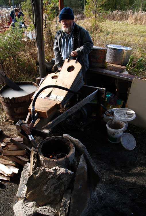
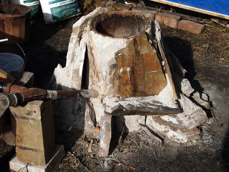
Smelter and Bellows System
Leather Y at Tuyere, Clay Furnace supported by stone slabs.
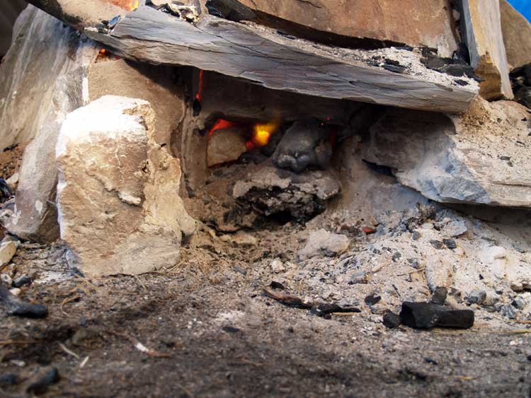
Later in the smelt, tap arch open showing slag bowl inside furnace.
Smelter: 22 cm interior diameter 55 cm tall 5 - 7 cm wall thickness construction of clay mixed 50 / 50 with course sand 'Boxed Short Shaft' - a clay cylinder supported by stone slabs, wood ash packing tap arch at 45 degrees to tuyere position
Tuyere: 2.5 cm ID steel pipe started smelt with end taper to about 1.5 cm ID inserted 5 cm past interior wall set at 25 degrees down angle interior tip set 15 cm above hard floor of smelter
Air: Human powered Norse style double bag bellows estimated air delivery (@ average one stroke per minute) 700 LPM Attached to tuyere via a leather Y joint, allowing both observation and ability to clear blockages.
Ore: Dark Dirt 2 analog (about 65 % Fe) 18 kg added Basic charge was 1 kg, added by 'standard scoop' at approximately 250 gm
Charcoal graded to normal ' golf ball to pea' size (through 2.5 and .5 cm grids) Basic charge was 2 kg, added by 'standard bucket'
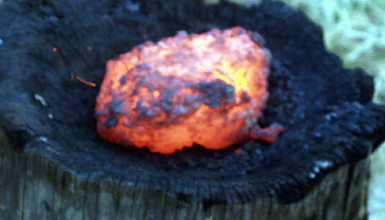
Production Bloom - 2.9 kg (after initial compaction after extraction) further 1 kg of lacy metal was recovered (mostly too fine to compact)
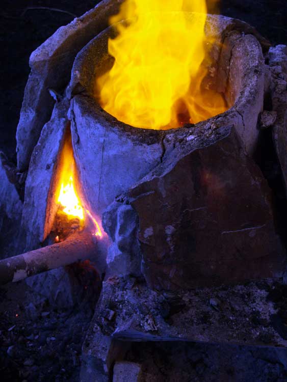
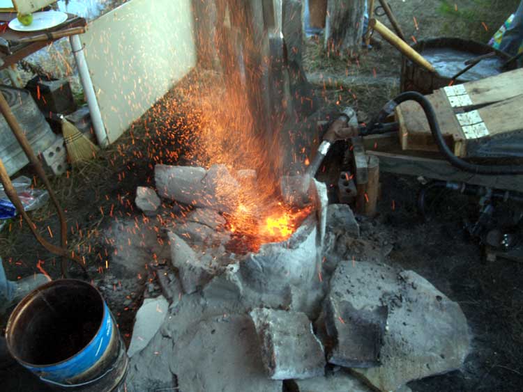
High temperatures above Tuyere.
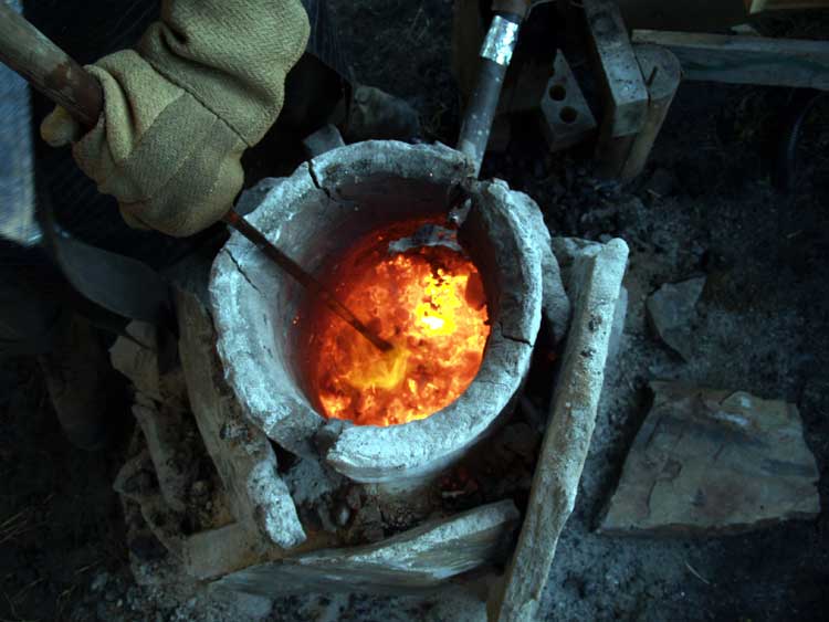
During Extration - bright mass to top of the smelter is the bloom.
Second sequence with the 'Thumper' to loosen the bloom.
General Notes:
The use of a steel pipe (standard 1/8 wall thickness) always results in erosion of the tuyere. Typically, this works back to the furnace wall, then causes significant erosion of the furnace wall itself. This was extreme in this case, the wall immediately around the tuyere was egg shell thin (about 2 mm) by the end of the smelt. At one point the wall burned through and had to be quickly patched. Continued use of our standard ceramic tuyere would certainly have avoided this problem.
The specially built 'smelting bellows' proved both easy to operate and able to produce volume required. There appeared to be some problem maintaining the correct pressure. Lower force levels used by some bellows operators resulted in an obvious shifting of the heat zone both towards the tuyere and also further up from the bottom. This in turn caused the slag bowl to sit higher and closer to the front than is ideal. Some problem with a shallow slag bowl attempting to drown the tuyere resulted, requiring tapping / modifying bowl position, especially early in the smelt. The most obvious solution is better training for the bellows operators to allow for more consistent air delivery. (This *was* our first use of human powered air since our very first attempts, some years ago. Many of the operators 'taking turns' had no experience with any type of bellows at all!) Increasing the angle of the tuyere slightly may also help with lowering the slag bowl formation.
This smelt also marked an absence of one modern aspect - time. In past experiments, elapsed time has been the main control point for our actions. For this smelt, a consistent air flow was established, and a set of standard measures for charcoal and ore used. The pattern of ore to charcoal additions was based on past experiences (rather than being modified to suit elapsed time). This did not appear to present a major problem, as the team has accumulated enough experience at this point to utilize other cues (primarily sound). One thing that did become obvious is that some counting method is required. Over the long course of a smelt, things like 'how many buckets since...' and 'how many ore scoops so far this bucket...' become difficult to remember. A simple set of stone counters is the suggested method for keeping track.
It was clear that the end segment of the smelt sequence was rushed slightly. It was decided to merely cover over the last ore charge added with a partial bucket. The reason for this was the extreme fragility of the eroded sections of the lower furnace walls. In the end it was found a significant amount of reduced metal did not have time to adequately attach itself to the developing bloom. This resulted in the loss of a good 25 percent of possible bloom mass.
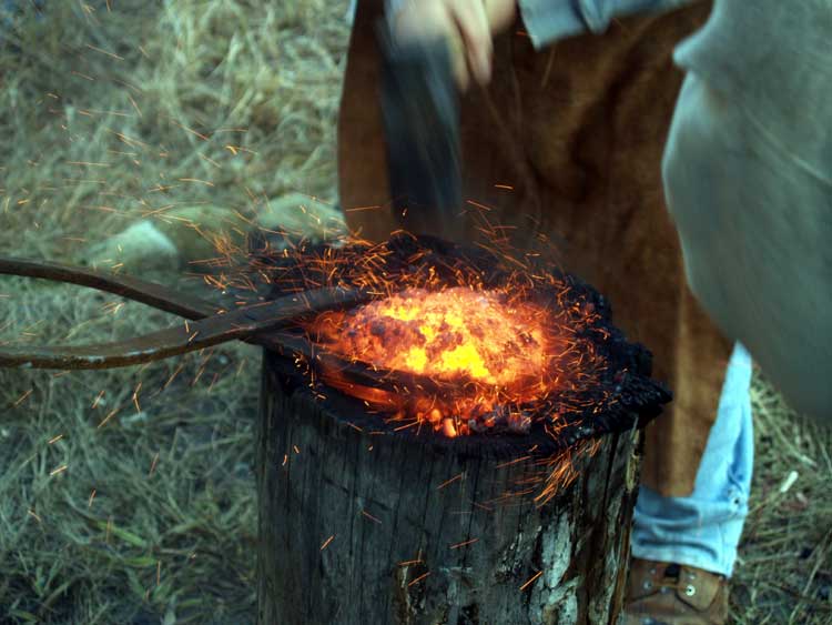
Hammering on the bloom to remove adhering slag, and compressing the mass.
Close up of bloom after initial compaction.
Despite these small problems, overall the experiment was a success. The bloom produced appears to be soft workable iron, and certainly closely matches the actual production by the Norse at Vinland which we are working to replicate.
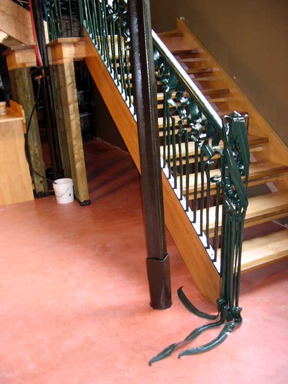
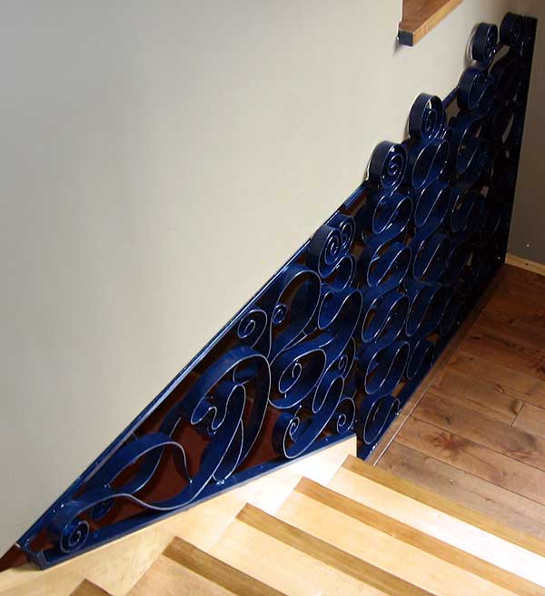
These images are from the second installation of the Reade - Maxwell project - the segments that run from the basement to the first floor. These elements comprise the 'undersea to beach' aspects of the overall 'Sea to Shore to Sky' theme of the project.
Standing in the basement, looking up through the open concept layout up the stairs to the main floor of the house, this is what you would see. The light from the floor to ceiling bank of windows along the south side of the house spills over the hardwood stair cases.
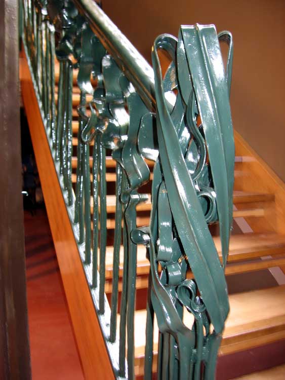
The bottom diagonal is a design inspired by sea kelp. The end newel post is a gathering of these leaf shapes, swirling in a spiral as if caught in a whirlpool. Each of the kelp frond elements progressing up the stairs is forged to an individual set of reversal curves. All the undersea sections are painted a dark green.
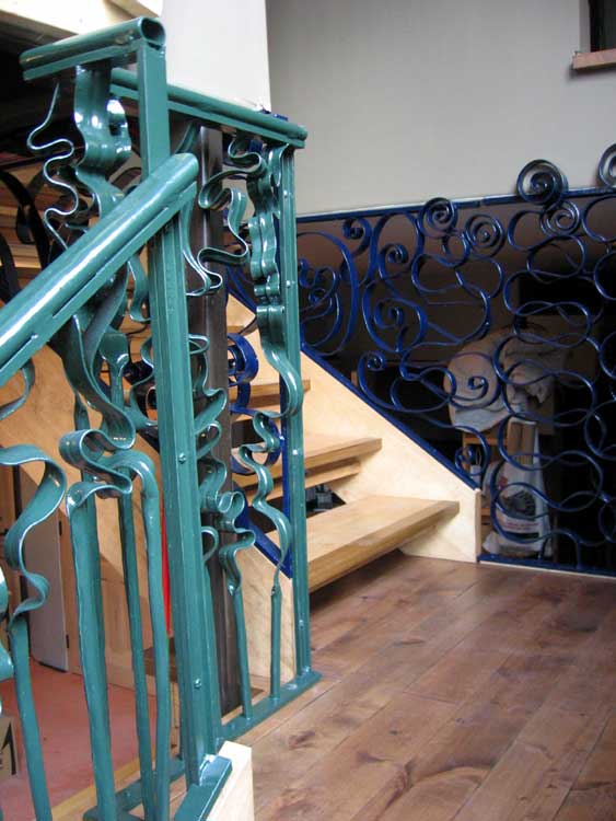
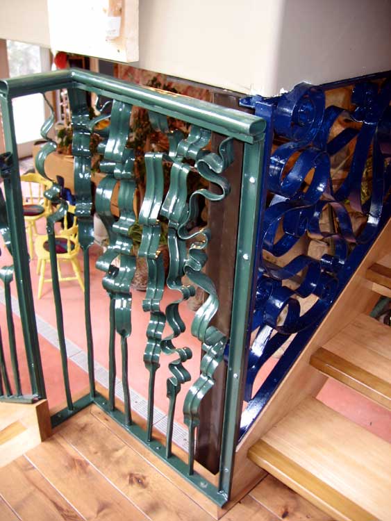
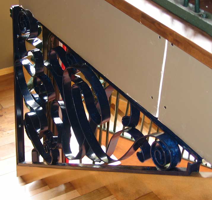
About two thirds the way up, there is a small landing, where the stairs turn a right angle. On the left, the kelp elements continue, the leaf sections getting longer and more chaotic. Turning the corner, the pattern changes to one of waves, now painted a deep blue. A sweeping set of reversal curves marks the undertow, sweeping up over the framing wall.
In detail, it can be seen that the right and left sides, although similar, are in fact unique patterns. There is depth to the swirling curves with their terminal spirals. Two quite separate layers on the more predictable undertow section, but merging to an interlacing chaos at the wave forms break close to the top of the stairs.
Looking up from under the landing, you can see up through the open work of the undertow pattern to glimpse the waving lines of rushes, standing along the shore line that marks the edge of the main floor.
Those following the blog in detail will have seen a large number of earlier posts related to this project, my primary work since April this year. Those interested should search under 'Reade Maxwell' to find these pieces (including a number of 'work in progress' video clips).
For the next in the Vinland smelt series, the material for the furnace walls has been changed. Course sand (dug locally) was mixed 50 / 50 by volume with the powdered potter's clay (Bell Dark). The finished furnace walls are roughly 5 - 7 cm thick.
View of smelter work area, boxed in to rough size of the Furnace Hut at L'Anse aux Meadows
Slack tub positioned to duplicate size and position of an unexplained large pit from the archaeology.
Using a 22 cm diameter tank as a form. End of the first course of clay.
Showing bricks placed inside to stablize the furnace, plus allow the tank form to be moved higher.
Packing the gaps with dry wood ash. This both helps the furnace keep its shape and draws the moisture from the clay.
Full height of build at 65 cm total.The exterior will be wrapped with sheet metal to prevent slumping.
I often get direct questions related to specific problems in blacksmithing. I often will turn those responses into blog postings (to share the information, after the work of writing them!)
...I saw your videos on youtube and in the one explaining your shop ''set-up'', I noticed you are using an updraft hood.. I've heard alot about side-drafts and how they do the job way better then the other one. I'm halfway done with building an updraft for my forge, and I was planning to use a power ventilator or something like it, to help it suck up the smoke. - Samuel
In case you have not seen it, the reference is to this YouTube segment:
Sam Asks: Does your hood work well? ...what kind of ''fan'' do you use?
I have a chimney set up adapted from an 1880s book on smithing. There is a roughly 12 x 12 square pipe that extends from the ceiling with a second piece about 11 1/2 x 11 1/2 , maybe four foot long, that fits inside this. The smaller section ends in the more or less chopped off pyramid that is the hood. Thats maybe a foot top to bottom and extends to about 2 x 2 feet on the lower edge. Originally this inner section was counter weighted. The cable eventually eroded in the coal smoke, so now it takes two hands to lift the hood. (The hood piece is not heavy, it just binds if you try to lift it with one hand.) A simple pin through a hole holds it in place. Now I can actually drop the hood tight on to the top of the forge table. That would pretty much get every last bit of the smoke contained. In actual practice, I lift the hood all the way up to give me about three feet of clearance for cleaning and setting a new fire. Once lit, I drop the hood down to about 18 inches above the forge table. This is quite effective for gathering the smoke during normal forging operations.
The use of a blower to extract smoke is important in this set up. In the ceiling space above the enclosed forge room, I had installed a large furnace squirrel cage blower. (These prove pretty easy to gather at the dump - at least around here.) That type of blower has two circular inputs - one on either side, and one large output in the middle. The output is roughly 12 x 10 inches. This is fixed to another section of rectangular duct that runs at right angles to the line of the chimney. In my case this piece sticks out through the end wall of the building. As the blower has two input sides, I boxed in the side opposite to the one attached to the forge hood. This ends in a simple trap door that opens down into the forge room on the ceiling. In warm weather I open this, thus pulling room air out at ceiling height. This not only grabs any smoke the forge hood might miss, it also pulls a lot of the hot air out of the room as well. Needless to say, come winter I need to work with that trap shut.
Exterior View: On the lower left (partially obscured by the tree) you can see the output vent from the blower. The straight line passive stack shows on the upper right. The wedge shaped piece of metal diverts our heavy snow fall around the base of the chimney.
Interior View: The retractable hood in the full up position. To the upper right can be seen the open 'hatch' that leads to the blower to extract room air.
Although this set up on its own does certainly extract all the smoke from the forge, I have also extended the line of the forge chimney straight up through the roof using a length of 10 inch diameter stove pipe. This ends in a standard fire place style cap (to keep the rain out). This second vent point actually will actually extract most the smoke during the forging sequence - passively.
I don't know exactly how much air the blower pulls - but it is a HUGE amount. Enough that you can not keep much heat in the shop come winter. This presents is own problems here in Grey County.
Sam Asks : Do all the side-draft (users) exaggerate the weak abilities of the updraft hood?
The problem with any side draft chimney set up is getting it built correctly. There is no doubt that a properly designed side draft will preform like a vacuum cleaner. I have seen some that will actually suck smoke back down towards it and out! The main thing with a side draft is getting the correct proportions of smoke hole to shaft size. To get that magic draw, the proportions of side opening to chimney square area needs to be in the range of 1:3 to 1:4. (So smaller opening than the size of the chimney) If there is not a large enough difference, the chimney stack will just not draw correctly. The exact details of the construction can effect the potential draw as well (like too much rough mortar left on the inside surfaces when using brick. All that being said, I have seen extremely good results using a straight piece of 10 inch diameter pipe with a brick sized hole cut in side. There is sure to be some relationship between the placement of the inlet opening above the forge table. Most I have seen are located with the bottom edge of the cut out about 4 - 6 inches above the table surface. A passive chimney set up of any kind is also effected by roof layout, local setting, variations in wind and weather. The exact placement of the chimney stack above the roof line is important, as is the orientation of the roof line to prevailing winds. Placement of near by trees can effect function of a chimney. Rain or dry, hot or cold, direction of wind a given day, all can combine to sometimes render even the best passive draw chimney ineffective.
One thing to consider (??) is that with a side blast, the chimney stack has to sit to one side of the forge fire, and fairly close to it. This may or may not interfere with the placement of a working piece into the fire as desired. Not a problem with smaller objects, or generally for linear ones. May be a consideration with larger 3-D pieces. (This is another reason I set up the hanging hood arrangement - I can work pieces potentially from all four sides of the forge.) Bear in mind that most likely the weight of your chimney stack will bear down on that side of the forge table as well. In the classic 'traditional' forge, the heavy brick construction is not because of the forge itself, but required to bare the weight of the brick chimney above. Of course there are ways to limit that, but now construction is becoming more complex overall. (Balance that against the light sheet metal construction of the galvanized sheet I chose for my set up.)
I think the comments about the weakness of the straight line, passive chimney are fair - when compared to a correctly designed (!) side draw chimney. However, my system is essentially a powered blower extractor. No real comparison in terms of raw volume of air moved between it and even the best designed passive system.
Sam Asks : Does your shop end up full of smoke?
No.
First off, remember that there is only a significant volume of smoke generated during the initial 'coking up' phase of working with a coal fire. I can easily lower that hood close to the top of the forge table, grabbing 95 % of the smoke generated for those first few minutes and the blower ramming it out through the side vent. That extra hatch in the forge room ceiling pulls out a good volume of room air - and any of the remaining smoke with it. After coking, working a fresh fire does not produce that much smoke. At that point I could actually turn off the blower and allow the straight line stack to passively vent the fire. (In actual fact, I just leave the blower on all the time I'm working.)
I had suffered lung damage from working in a living history museum (unnamed for liability issues - but its the large one in Toronto). The health standards there were absolutely Victorian. The management at the time acted as if they thought Ontario Health and Workplace Standards did not apply to them! I quit that position, the longest season and highest paid artisan interpreter job in Ontario, largely over these horrible safety conditions. The problem there was two fold: First, the chimney itself had been built like a fire place - NOT correctly like a forge. The chimney actually tapered in smaller for the first three feet or so. This resulted in hot air being piled up as it tried to enter and rise, filling to overflowing with smoke. To make matters worse the proportion of bottom opening to stack cross section was almost exactly backwards. The straight stack section (above the constricting flare) was about 10 x 12 inches. The opening at the bottom was about 16 wide by 18 inches high (so a 2.4 : 1 ratio - against the optimal 1:4!) Second, the chimney top was : - located on the east side of a building with prevailing winds from the west - ended lower than the building ridge line - a tree on the west side had grown up to almost 1/3 higher than the building peak. The net effect of all that was that nine days out of ten, the wind blew over the top of the tree, slanted down on to the building ridge, then effectively blew back DOWN into the chimney. This was such a problem (compounded by the management's insistence that it was all due to my lack of skill!) that I ended up contacting over 30 other living history museum blacksmiths from all over North America, I got replies from most of them describing their own forge and chimney layouts for comparison.
Anyway, the short (after the long) of this was that when I established the Wareham Forge as a full time business and constructed my own workshop, I was painfully aware of the dual problems of coal smoke and chimney construction. The use of what is basically a simple powered negative pressure system for my forge is a result of all this.
August 29 - October 10, 2016 : 'Turf to Tools Two' Project Grant
Canada Council
August 2014 : 'Turf to Tools' Travel Grant
Ontario Arts Council
February - May 2012 : 'Bloom to Bar' Project Grant
February 15 - May 15, 2012 : Supported by a Crafts Projects - Creation and Development Grant
COPYRIGHT NOTICE -
All posted text and images @ Darrell Markewitz. No duplication, in whole
or in part, is permitted without the author's expressed written permission.
For a detailed copyright statement : go HERE
 Primary Bog Iron Ore, sample from St Lunaire, Newfoundland (after roasting)