Friday, December 31, 2010

Interpreting an Artifact

- The Mastermyr 'Fire Grid' as a case study

'The Mastermyr Find' by Arwidsson & Berg * is one of the standard references for anyone interested in functional iron work (especially tools) from the Viking Age. The find consists of a wooden chest containing a complete set of blacksmithing and woodworking tools, as well as a number of both completed metal objects and pieces obviously under repair. The volume describes the find, which was unearthed by a farmers plow in Gotland, 1936. As a primary archaeological report, it contains scaled drawings, photographs, written descriptions and contexts for all the objects. Although originally dated to 'late Viking Age' (circa 1000 AD), later examinations have pushed the tentative date for the deposit to closer to 1150. This does not change the fact that the majority of the tools particularly are types in common use throughout the entire Viking Age.

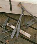
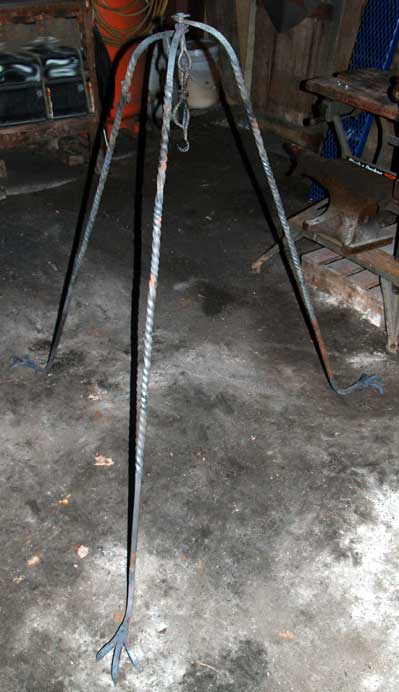
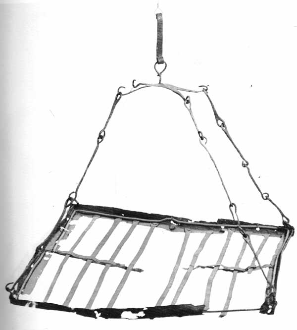
The object under consideration here is the large 'Fire Grid' found in association with the tool chest. Obviously it would not fit inside the box itself, the rough measurements of the grid are 50 x 50 cm.

Even when working with as good a primary source as The Mastermyr Find, I find it extremely helpful to scan in the available drawings or photographs. Photographs often reveal details that don't get interpreted into drawings.


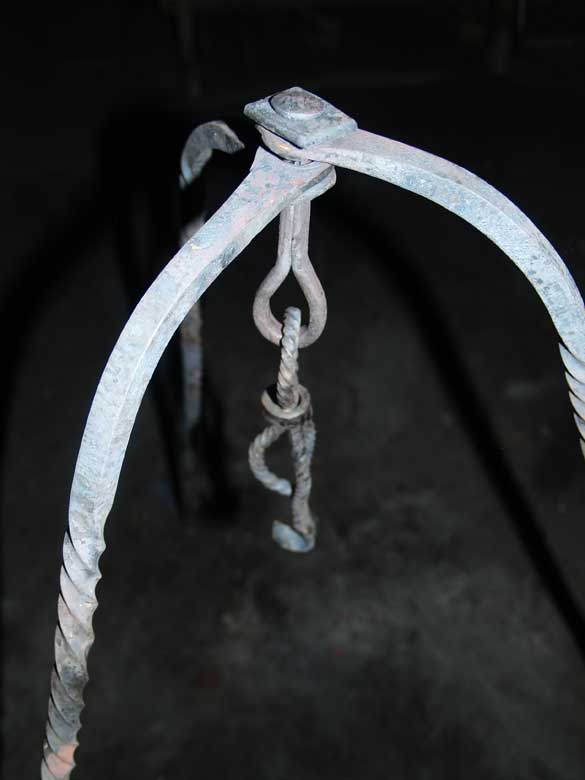
Photograph of the Fire Grid

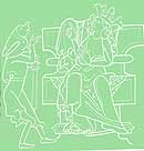
Drawings are helpful, as they usually are scaled. I will typically then go back into the text descriptions, and transfer those details back directly on to the printed drawing. Like many of my generation, I grew up with both metric and imperial measurements. I also tend to use metric with artifacts, but need to revert to imperial for practical work in the shop. So I will convert the provided measurements to have both types available. Sometimes this will include taking written measurements and generating my own life sized illustrations.


Scaled drawings with preliminary notes

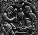
Even as often as I work with artifacts and replicas of them, I'm always amazed when I manage to get the actual artifacts in front of me. Everything always seems either much larger - or much smaller, than my best impression. For that reason, I will convert all or part of the available images to roughly life sized copies.


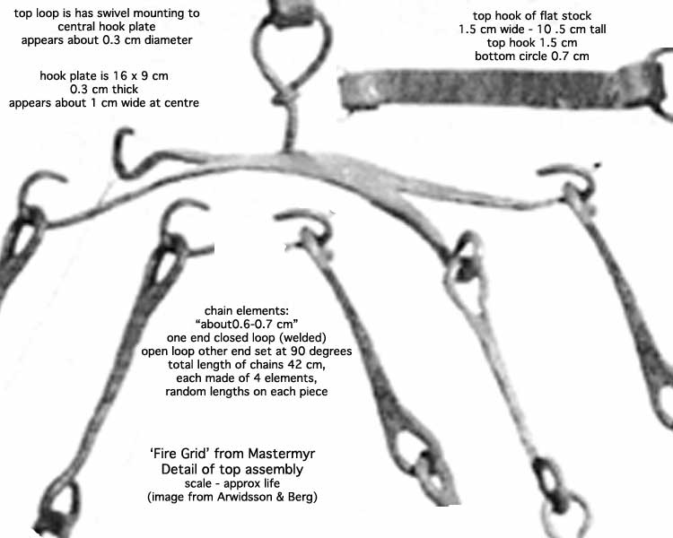
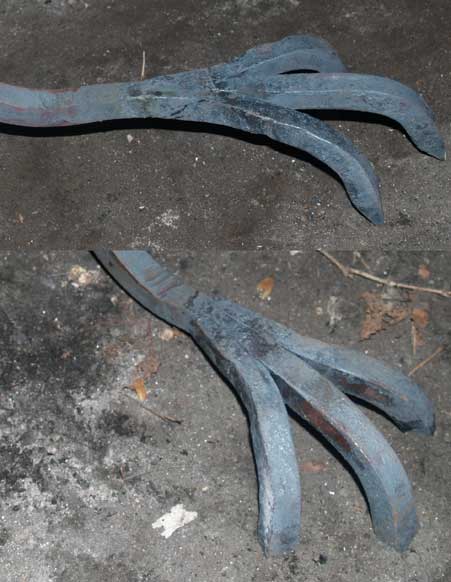
Expansion of a detail to life sized.

If I am am actually going to duplicate an object as a replica, I will also often make a set of 'scale as' three view production drawings. These I can take into the workshop. I find it extremely helpful to see exactly the size of the individual elements which then combine for the finished replica.

With all this information in front of me, what information can be gathered and interpretations made?

The first thing was that I found a printing error in the written description. The measurements give : "Frame about 50 x 50 cm; strip width 0.45 cm, thickness 0.25 cm; grid rods 49.0 X 1.2 X 0.3-0.5 cm." Looking at the photograph it is quite obvious that the framing is about twice as wide as the individual grid bars, not half the width as indicated. Change that measurement to 4.5 cm, and it better conforms to the proportions on the scale drawing.
Keeping at the frame, converting the revised measurements into a cross section makes that piece roughly 1 3/4 inches wide by 1/8 inch thick. It is hard to see if the L stands as tall as it is wide, there is no detail cross section drawing, and the height measurement is not given.
The individual cross bars are fairly light in construction, at only approximately 3/8 inch wide and 1/8 inch thick. The central 're-enforcing' strips are even thinner, closer to 1/16 inch thick (by the scale drawing).

The dimension of the chain elements is given as 0.6 - 0.7 cm (about 1/4 inch). Although not described as rectangular in cross section, the photograph certainly shows these are irregularly forged to shape. Some of the individual elements range in both size and construction, suggesting repairs. (The description does mention that there are other obvious repairs and breaks to the object overall.) If you look at the front left and rear right chains, these are the most consistent looking, and so may represent the original elements. The individual chain pieces have one solid loop on one end, the other an open (tapped flush) loop rotated at 90 degrees. The closed loops look to be forge welded shut (the method expected using bloomery iron at such small dimensions).

The other top elements are not described in great detail.

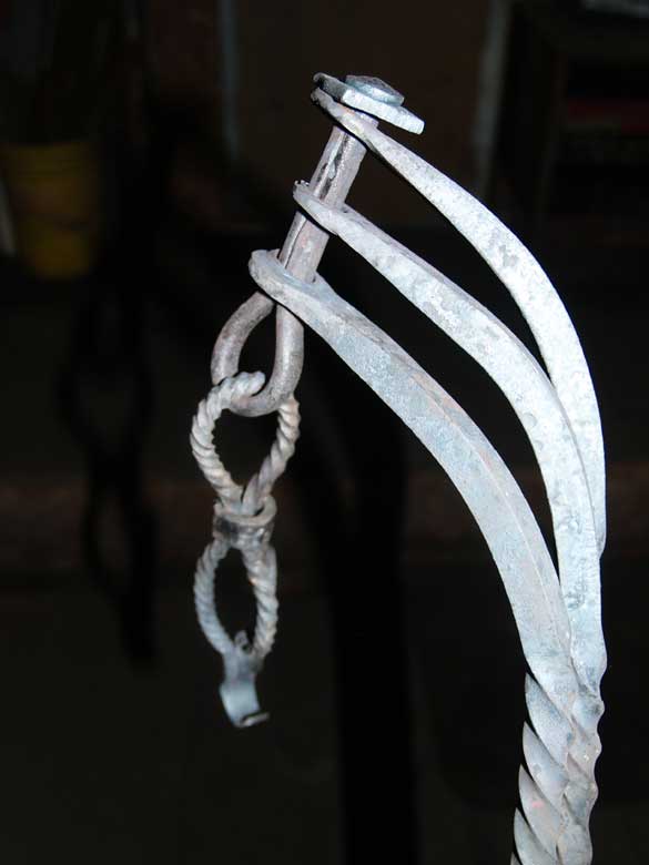
The rectangular top plate has its length given at about 16 cm, width at 9 cm and thickness of 0.3 cm. The width given is obviously the dimension at the full spread of the hook ends. It is pretty difficult to correctly estimate the width of this bar at its centre, working from an angled perspective on the photograph, and the perspective on the drawing is obviously distorted. My best guess, working from indications from both (which more or less agree) is that the width at the centre is roughly 1.8 - 2.0 cm.
That means the starting bar would be about 3/4 x 1/8 inch, about 2 inches for the centre, extending to forks about 4 inches long and about 1/8 square at the tips (flat to square profile). This material is bent back for the individual hanging hooks, each about 1.5 cm ( 5/8 inch ) in diameter.


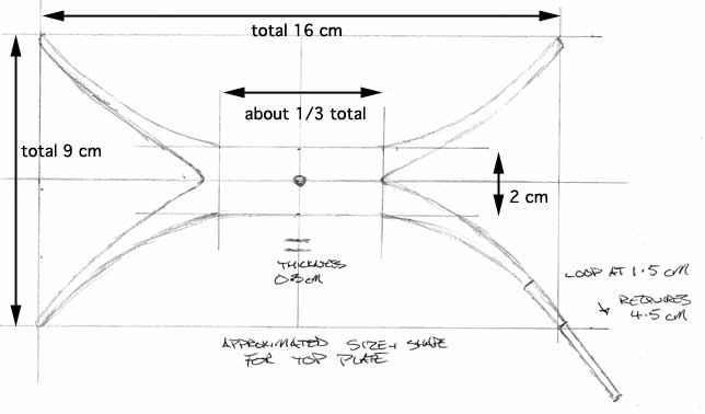
Estimating the size of the top plate

There is also a length of round profile rod which is formed into a swivel loop. The end of the material which forms the loop is simply wrapped around the upright stem to secure it. The other end of this rod goes through a small hole punched in the top plate, then appears to have been upset to create the 'knob' which secures it. Although the diameter of this element is not given, from the scaled up photograph, it looks to be about 0.4 cm (a bit larger than 1/8 inch).

The very top of the support system is an extremely simple hook formed from a piece of flat bar. The starting material is 1.5 cm wide, and the thickness is not given The diameter of the top hook is given at 1.5 cm wide, the lower loop appears to be 0.7 cm in diameter.

INTERPRETATION

Berg specifically describes the fire grid (number 31) as a lighting device, and links this piece to a number of other existing samples found in northern Europe.

Overall, the construction of the entire object is quite light. Many of the individual elements are simply too small, the materials used too thin to provide much structural strength. Remember that all of this material is composed of bloomery iron, a material with considerably less structural strength than our modern metals.

This is most especially evident with the top plate and the swivel loop elements. The weight of the entire lower grid is supported by four small loop hooks on the ends of the top plate. Further, the entire weight is finally supported by the single small swivel loop, formed from round profile material only 0.4 cm (less than 3/16" inch) in diameter.

Many re-enactors desire a 'cooking grill' for their camps. This artifact is most often pointed to as the historical reference. It is clear from a detailed look at the construction of the actual object, that it could never serve that function. Its relative light weight further supports the ethnographical references given by Berg in the primary report. This object is better suited to hold light pine knots serving as a source of area lighting, likely for a workshop.

The concept of using a metal grill to support cooking pots, or for grilling meats, is much more modern than the Viking Age. It is certainly better to have an object in a camp that looks somewhat historic, so certainly a replica based on the Mastermyr fire grid is a better choice than a purely modern cast iron cooking grill. Grilling meats 'BBQ' style is certainly not a Viking Age method of food preparation.

I would suggest that re-enactors interested in the highest levels of authenticity in their presentations consider deeper research into the actual foods and food preparation methods used during the Viking Age.


* 'The Mastermyr Find - A Viking Age Tool Chest from Gotland'
Greta Arwidsson and Gosta Berg -1983
Almqvist & Wiksell, Stockholm Sweden
91-7402-129-X

Tuesday, December 28, 2010

Revisions to the 'Norse Encampment'

Before Christmas, I started working on re-vamping the existing documentation for the Norse Encampment. The original information was placed on the Wareham Forge web site back in the late 1990's. Even at the time, it was primarily text, rather than graphics, based. As over the last two decades, Norse Living History and Replicas have become one of my unique specializations, I thought it was well past time to upgrade that section of the site (makes about 25% of the total).
Visitors need to bear with the ongoing changes, which will include new materials and inclusion of far more images. Most importantly, there is a new, hopefully easier to navigate index system, grouped by topic areas:


the Norse Encampment

Living History for the Viking Age

A BRIEF INTRODUCTION

The 'Norse Encampment' is the collective name given to a series of living history programs, starting in the early 1990's, which illustrate daily life in the Viking Age. Historic interpreters, employing replica objects, bring the past to life through typical activities of the Norse. These interpreters speak as voices from the past, portraying historic styled characters. Throughout the series exceptional care was taken to ensure everything involved in a presentation was reflective of current archaeological research. One cornerstone of all the presentations was reference to the Vinland voyages by the Norse, circa 1000 AD.

The collected information within the Norse Encampment documentation has been grouped into a number of topic sections (as seen to the right).
Individual articles may be included in more than one section. Your location in the series is indicated by a pale blue outline for the topic section.

Latest Revision / Addition : December 2010

Visitors to this series may find some disruption to some of the content
until full revisions to this series are completed!


Encampment INDEX

LINKS

L'Anse aux Meadows NHSC

Artifacts and Replicas

A Teachers Guide

Research

Interpreting the Viking Age

Experimental Iron Smelting

Dark Ages Re-creation Company

from the Wareham Forge

Saturday, December 25, 2010

Log Rack - a tale of Client interface & Pricing

Sometimes, you just can NOT replace a face to face meeting with a client!

This saga is presented not by way of grumbling, but as a informative tale to young artisan blacksmith's, and hopefully to help potential customers understand both the design and pricing process for a commission.
I would like to see about a commission for an indoor wood rack to put beside a wood stove.
It would fit in a tiled space beside the stove... my husband wants to cram in as much wood as possible, and I want it to look beautiful.
so It seems that 46-48" long 48" high and 12-14" deep. with only one end (facing into the room) loking beautiful ...
I looked at the "enclume" ones online and that size runs $250. would it be possible to get something for twice that? and would it be possible to get it before Christmas?
I had this request forwarded to me from my close friend David Robertson (at Hammer and Tongs) who is currently working on a major public commission piece. As we often do, if either of us can not undertake a project (usually due to scheduling) we will refer to the other.

It took a bit to get in contact with the customer, and on December 3rd we had started the consulting process, with this additional consideration.
and...I have found out through sublte snooping that he would like 2 sections so that one pile would dry while the other section is being used.
The commercial log rack the customer had been looking towards is made by Enclume. This I found via a fast google search. (A note to potential customers, I can usually find the original source descriptions when you 'ask to make something like this' - just as easily as you did.) Specifically their 'Arch Rack' It is described as 'our largest at over three feet long' ( actually 38"L x 13"W x 30"H). It has a manufacturer's suggested retail at $220 US (without shipping). As a commercial product, it is designed to pack flat for shipping. Each of the two end arches are held to the lower frame with only two bolts, set at the bottom edge.


Now, although much of the weight of a log rack is down through the feet, there is also considerable stress pushing sideways, against the end pieces. I had a number of purely structural concerns about scaling up the size to the final customer's request for 40 inches long by 40 inches tall:
1) Stability - base footprint against height. The desired unit would need to be no more than 12 inches wide, to hold standard firewood cuts (range from 14 - 16" normally). However I was greatly concerned that at 40 inches tall, the rack would be unstable. If that weight of wood should fall outward, it would pose a major safety hazard.
2) Point Force - The commercial rack had quite small legs, so considerable downward force was being exerted over a very small area. If the rack was extended even taller than this, then the rack placed on the slate tile surface seen in the photo, I was concerned the slate might actually break.
3) Sideways Force - I recommended a rigid frame, or at least very heavy structure, to resist the potential sideways force exerted by the large pile of wood. This narrowed designs to rectangles placed 'on edge' or contained shapes (framing at top as well as bottom).

Admittedly, I was initially pre-occupied with these structural concerns. I did have a lot of problems communicating these restrictions to the customer. (Note that all this was done via the internet, the customer did not have a fax. This process was extended because the early December storm effected our internet connection here in Wareham)
I produced an initial pair of possible designs, as 'three view' drawings, with accompanying written descriptions :
The first uses single lengths of 1/4 thick by 1 1/2 wide flat bar, forged into a U shape. These are placed so the stress runs directly against the width of the bar.
The second (my favorite) is a pair of large ovals, placed to angle slightly into the centre. This design would have been the most difficult to forge, as the starting material would be some 12 feet long! Both these designs have the advantage of having the weight spread along fairly long strips running the full length (roughly 40").


At this point I got this image from the customer, showing the intended installation location. This proved to be of great value in terms of understanding the dynamics of the space and potential limitations.
From the start, I had was considering the view of the rack towards the long axis. The customer, as it (much) later turned out, was concerned about the view towards the narrow end - from the open room. This basic difference in viewpoint would be the source of the communication problems!
Now, at this point the customer also mentioned something about 'hoping it would fit into the car'
Back to the design board. I concentrated on a layout that would be structurally strong, yet disassemble into smaller units which would all bolt together. Now understanding that the end panel 'art work' was a major concern, the resulting design would allow a separate decorative piece to be constructed and bolted to place. The rear 'wall clip' was a potential solution to the stability problem.


Well - (admittedly) that was just too plain. The customer liked the use of the spear point U shapes from the initial design. Was there any way to incorporate these? Oh, and maybe the height can be reduced if there was really a problem with stability. That plaster wall had a pocket door inside it, so really did not have any structural framework to tie into either. Oh, can there be a gap between the bottom of the frame and the floor to allow for cleaning underneath? There should be a gap between wood and back and side walls to allow for drying ventilation.


So this is what I came up with. With the flat bar turned on edge now, it needed to be strengthened (force against the 1/4" thickness, rather than 1 1/2 width). Welding on lengths of 3/4" angle would solve that one. I determined that since the wood was at least 16 long, the legs could easily be that long as well. With the functionality of a rear wall bracket questionable, the customer determined that maybe only 30" tall would do. Perhaps a bit over engineered, I added the re-inforcing triangles (greatly increasing the amount of welding required).

Well no - "I wanted the flat pieces to run the other way" As in parallel to the 40 inch long face towards the wood stove. "But then you would only see the thin edge, I though you were concerned about the view from inside the room?" , said I.
Back to the drawing board (again)


Version 5 - the final. A variation on number 4, with the uprights now turned along the long axis. This solved the structural problems, yet allowed me to simplify the construction. You can see individual elements from the earlier designs continued.
Finally with a design confirmed, a deposit was made, and the physical construction was started. There was yet another design task, which was for the 'art work' panel for that open to the room end. Either through good luck (or fatigue) the customer approved my initial concept.


I had a piece of expanded aluminum sheeting that was just the right size to fit on the top as an accessory shelf, so included this in the package. This was the end result. (Note that this kind of thing is hard to photograph , these are not the strongest images).


Next - Pricing considerations:

The back and forth and re-design phase extended to December 17, that was a total of at least 14 days. Dozens of e-mails. You can see a total of 5 individual designs were produced, each with an associated scaled drawing, written description - plus a cost quote. Time for each design & quote : about one hour. Normal published price rate for design work is $50 per hour. So, one question : Do you charge for ALL the design work (total of about five hours) or just for the final designs employed in the commission (about 1 1/2 hours) ?

The original request was for the piece to be completed by December 20th. I managed to have the piece completed (including time for paint to harden up) for potential delivery on December 21. No problems on that score.
One aspect to consider here however : The delivery location is Orangeville. Elapsed distance / time from Wareham, 150 km / one and a half hours. Cost of the gas : about $30. Do you include a delivery charge?

On the work itself:
I normally quote a piece based on three separate methods -
1) Actual working hours - based at $75 per hour shop rate. (I don't actually quote an hourly rate normally)
2) 'Production days' - based on $200 per day. This is what actually gets done around here in a given day, so includes record keeping, communications, supply runs - and sometimes actual forge work.
3) 'Per element' - a rough price for each activity, then add the number of steps.
Remember to add in the cost of materials (at replacement)!
Now what I have found over the years that these numbers will calculate out pretty darn close to each other. It does give me a check to ensure I have not over (rarely) or under (more common) charged on the quote.

And don't forget the cost of materials! This is a mistake I make way too often. Large size stocks, structural shapes, components like stainless or copper can add up pretty darn fast.
Painting may seem pretty simple, but does it ever add up a lot of time, especially when hand painting complex forged shapes. My own experience is that no matter how careful you are, you almost always 'miss a spot' and end up going over the whole thing twice on the top coat. (A useful bit of advice, make sure you make that last check with the object in its final install position - what the customer will see.)

So these were the quotes for the individual pieces (does not include a design fee):
1) Open Top U - $615
2) Ovals - $630
3) Square - $405
4) Sideways U - $575
5) Spear Frame - $450
Additional
6) 'Sheaf' panel - $150

Now - how does one of the estimates get produced, using the final chosen design (Spear Frame) as the sample?
1) Shop Rate - total of 5 1/2 hours @ $75 = $412.50
2) Production Days - total of 2 1/2 @ $200 = $500
3) Per Element
a) Estimated - forge ends uprights - 6 @ $15 = $90
- top frame - 6 @ $5 = $30
- lower frame - 12 @ $5 = $60
- legs - (2 @ $5) + (6 @ $ 15) $100 ($280)
plus - paint - $25
- materials $100
TOTAL $405*

b) Actual 'medium' forge heats - 42 @ $5 = $210
welds (MIG) - 46 @ $1 = $46
cutting - straight - 16 @ $1 $16
- diagonal - 10 @ $1 $10
- slots - 2@ $10 $20 ($302)
plus - paint -(actually took a full hour) $50
- materials $100
TOTAL $452

On the 'Sheaf' panel, my published rate on decorative panels is $100 per square foot. I agreed with the customer to work with a lower budget :
Estimated -forge uprights - 6 @ $1 = $90
- forge ribbon - $25
- weld and paint - $25
- material - $10
TOTAL $150

* This was my own 'ball park' estimate total. I normally add on 10% additional for 'unforeseen' on any given project. This made the total quoted to the customer $450.
The two figures in brackets represent my estimate of the work total against the actual 'per action' total, which you can see are within 10% of each other.

So in the final, I billed the customer for a total of $600. The initial budget restriction was for $500. The customer paid a bit more (primarily to cover the addition of the decorative panel). I ended up absorbing the time spend on all those extra designs. The customer was quite pleased with the final piece when it was delivered.

Tuesday, December 21, 2010

History as Music Video

These are making the rounds, but frankly - they are so wonderful I thought I'd add to the viral and post a couple here:

The Vikings ("Personal Jesus" by Depeche Mode)


Beowulf ("99 Luftballons" by Nena)


These are by the group 'History for Music Lovers' - the History Teachers YouTube Channel. ABSOLUTELY worth checking out! (Direct Link to YouTube)

Of the ones I've watched (although they are all great!) my favourite so far is:

The French Revolution ("Bad Romance" by Lady Gaga)


(frankly, I can't believe I didn't pass this along earlier!)

Saturday, December 18, 2010

Inuit meets Norse

Fellow An Droichead member Catherine Crowe sent me a link to the work of Abraham Anghik Ruben.

This is an interesting viewpoint on the possible interface between what would have been the Thule culture and the Norse in the high arctic, in the centuries after the founding of the (south) Greenland Norse colonies. The Thule themselves were 'invaders', travelling from the west from Siberia across the high arctic (displacing the resident Dorset culture) See an earlier posting : Thule versus Norse

Abraham Anghik Ruben documents a series he calls : Inuit-Norse 930 to 1400 AD


Iceland 900AD, 2006
Brown Soapstone

Hunter and Seamstress II, 2006
Soapstone

Sunday, December 12, 2010

(Oversized) Oseberg Tripod Replica

As regular readers know, I have commented a number of times on the Oseberg Tripod. At best I consider this to be a cultural and archaeological puzzle ( I think a 'Damthing' ). Certainly, for a number of reasons, it is NOT a object that we in DARC include in our interpretive displays.
This is a scale drawing of the size of the artifact tripod, with rough profiles of the cauldron actually found with it in the burial, and the (much) later copper pot from Mastermyr as a comparison.
The fire bowl below is a common re-enactors solution to the modern restriction - 'no open ground fires'. This line drawing was prepared as a discussion point for the commission piece seen below. The customer's desire was for a Oseberg styled tripod, only standing tall enough to effectively use the fire bowl diagramed.


The solution was to increase the overall size of the tripod by about 30 %. I recommended that the diameter of the legs also be increased, from roughly 3/8 inch on the artifact to 1/2 square stock on the replica.
One special detail is seen with careful examination of the twists. The original artifact was created in a charcoal fire, which has a much smaller 'effective heat diameter. To mimic this, the length of the individual twisted sections was limited to 10 cm.

The design of the tripod is such that there is minimal possible alteration of the 'spread' of the legs. One restriction is the design of the upper pivot point. The top of each leg is curved, then upset and punched. A single looped piece is inserted through these holes, then the top of the loop is hot peened over. In my version, a square cut piece forms a simple washer. From the loop descends the orimental basket hook, these elements forge welded into a single unit.


A closer look at the top elements, with the tripod legs swiveled over - 'packed for travel'. To make the loop, I started with a length of 3/8 inch round, which was forged into a bottom die to create a half round shape. This was folded back on itself and the free ends forge welded together. This end was then dressed to create the 'pin' which threaded back through the holes punched in the top ends of the individual legs.

The basket is formed from two lengths of 1/4 inch square, each twisted. The longer piece was folded back over on itself, then the three stacked ends forge welded together. After these were forged to the basket shape, a short piece of flat stock was used to make the central collar. (Note my maker's mark on the side of the collar.) Last the welded block was drawn out and shaped to the hook.

The tripod legs end in this three clawed foot. To extra short pieces were forge welded to the main upright, then curved. Note how the foot is carefully angled to that it will sit flush with the ground when the three points of the claws are driven into the ground. This is easily done by simply stepping on the 'instep'.
The angles on the foot and at its attachment to the leg are such that they conform to the angle set by the curve at the fixed top of the tripod.

Wednesday, December 08, 2010

A Public Service Announcement ...

To my frequent readers:
'Hammered Out Bits' got hit with spam comments today. Some 36 over the last 12 hours, distributed randomly through past articles mainly over the last year. You can tell as the sender is named as 'viagra' or something related, and the name is actually a blind link to a sales site.

To try to halt this, I've switched 'ON' the comment moderation feature. Normally I just let you all comment as you will (heck, its not like *I* don't refrain from 'calling them like I see them'!) Although its a bit of extra work for me, I'll try to let your (normally valuable, or at least interesting) comments pass through the system.

Now back to your regularly scheduled programing...

Tuesday, December 07, 2010

What its NOT -

Is 'pattern welding' !!!


Now, I have spoken about this before. Frankly I get pissed off at people who incorrectly use language - especially if the advertising value appears the primary reason

" The term "pattern welding" can refer to any two types of steels that are welded together, regardless of the layer count or pattern.

A sword with composite twist core is simply refereed to as a "composite twist sword"

All of these terms are extremely loose because for the past thousand years people who dont make swords but only read about it misuse the terms and thus create confusion. But such is the history of silly feeble human language... :) "


That comment, by the producers of the extremely slick video offering above, does nothing to correct my impressions. 'People who make swords' here OBVIOUSLY need to do a little research. Specifically because THEY are the ones who 'misuse the terms and thus create confusion'.
I suppose I should not expect much, as smiths involved here are obviously too young to have even been born when the original 'rediscovery' of actual pattern welding techniques were painfully learned (ie, the 1960's and 70's)

What is being made here is about as simple as it gets. A low layer count, flat stack, single weld. Drawn out to a bar, no folds or additional welds, all machine forged. Not that the result does not look nice. But PATTERN WELDED it is most definately NOT .

(After Kristopher's comment below)

Increasingly, especially since the late 1990's, blacksmiths have been using what is TECHNICAL language as mere 'advertising'. I think this is an absolute plague to our profession. There are a number of reasons for this - perhaps worthy of a long commentary of itself.
Anyone truly interested in this problem should read my earlier commentary 'Defining the Artist Blacksmith'

(another addition)

I had prepared a lengthy discussion of the different technical terms that are applied to the field of 'layered steel' earlier this year (after the last time this question came up). See Layered vs Pattern Welded - Forge vs Foundry Those who really want to delve into the whole area might also search the blog using "pattern weld" or "layered steel". Either search will yield you another dozen related commentaries. ( I seem to get a serious question about this whole mess every six months or so!)

(yet another addition)

Mad Dwarf Workshop is the team behind the YouTube clip. Their website

Monday, December 06, 2010

Piles of JUNK paper!

What is the frakin' point of using compact florescent bulbs - when Industry (helped by Government) maintains this kind of excess:

Friday is 'Flier Day' via our Canada Post delivery here in Wareham. This is what we got in our box on Friday, December 3:

Store - Size - Location - Distance

No Frills - 3 sheets - Shelburne - 25 minutes
Foodland - 4 sheets - Dundalk - 15 minutes (our local)
Foodland - 4 sheets - Dundalk - 15 minutes - DUPLICATE ABOVE
Wallmart - 6 sheets (glossy) - Orangeville - 45 minutes
Wallmart - 3 sheets - (glossy) Orangeville - 45 minutes
Food Town - 2.5 sheets - Markdale - 25 minutes
Food Basics - 3 sheets - Shelburne - 25 minutes
Staples - 4 sheets - Orangeville - 45 minutes
Staples - 8 sheets (glossy) - Orangeville - 45 minutes
Marks - 8 sheets (glossy) - Orangeville - 45 minutes
Sears - 5 sheets (glossy) - Orangeville - 45 minutes (catalogue)
Sears Sears - 1 sheet (glossy) - Orangeville - 45 minutes (catalogue)
Sears - 3 sheets (glossy) - Orangeville - 45 minutes (catalogue)
Sears - 8 sheets (glossy) - Orangeville - 45 minutes (catalogue)

Canada Post wrapper (24 x 24 blank heavy newsprint)
Which is not being counted, as I save these for drawing around the shop.

There was also ONE piece of addressed letter mail, which itself turned out to be (useless) advertising.

The total weight off all that junk was 410 gms - almost a full pound.
For each household.

According to 'Standard Carbon Resources'
( http://www.standardcarbon.com/resources/?p=66 )
the carbon footprint for a single piece of 8 1/2 x 11 copy paper is .0092 lbs CO2, so each of the 'sheets' above represents approximately 8.35 gms of C02.
There are 67.5 sheets total, so that makes approximately 126 gms of CO2 total.
Thats just the physical material itself.

Printing?
Transport?

Now, I did spend a good half hour on the web, trying to find ANYTHING else which might clearly give me some numbers on the associated environmental impact. Not a hope. Lots of hype - no NUMBERS. I am very sure that the printing and especially the transport aspects strongly overwhelm the mere paper material in contribution to global warming.

Given our location in the wilds of Central Ontario, the cost of trucking collected paper for recycling is sure to greatly exceed the value returned via that process. I did see something that suggested that when placed in land fill, 90% of the material proportion (at least) remains locked up in the ground.
We normally burn our waste paper. We have electric heat here (baseboards), which when we bought the place over 20 years ago seemed the best option. (Thats how the house came, oil and propane furnaces would be the other methods possible here.) Our wood stove reduces (significantly) our electric heating. That power comes essentially from Bruce Nuclear. (Which I'm a big supporter of, ok?)

Recycle all that paper? Or burn it and reduce (slightly) our fire wood consumption? I say that sitting in a room that has daytime thermostat set at 16, night time at 12.

Maybe just a hell of lot less junk mail produced and delivered in the first place!


Sunday, December 05, 2010

Bit of a Facelift....

Mainly additions down the side bar.

As the Wareham Forge web site is now my primary means of contact for PAID work, I thought the large amount of time I spend writing and formating over here should have at least a FEW links back to 'what I do for a living'.

Friday, December 03, 2010

Reality and YouTube


Sometimes its hard not to rage against the 'world as it is' against the 'world as it *should* be'. More and more I find I'm becoming the 'old guy'...

Take YouTube.
I have a large number of available film clips available. At current counting there are 25 in total. (See my 'channel' : DarrellatWareham )
Of those the breakdown is:
Iron Smelting - 8
Blacksmithing Work - 13
Viking Age Work - 7
Fluff - 1
(some double up in those categories)

Now, what *bugs my butt* is people complaining about the video / audio quality:
Film Critics: PLEASE READ BEFORE COMPLAINING ABOUT VIDEO / AUDIO QUALITY
Please realize that I am an ARTISAN BLACKSMITH not a FILM MAKER.
Deliberate choices have been made to record information details, and the nature of the events depicted is effected by limited equipment.
Sound is recorded as 'ambient' - as I feel the sound of hammer on metal is a critical piece of information. This means problems with shifting volumes and background noise like fans and blowers sometimes intrudes.
Almost all camera systems use some form of infra-red focusing and what is depicted is hot metal. So of course focusing often shifts.
Cameras 'see' a different range of light than the human eye. The result of this is a flaring and inaccuracy when recording hot metals.
I deliberately choose to narrow the view to the working tools. The intent is not to display myself, but my work methods.
The video segments presented here are intended to be Educational - not Entertainment.
What I see here is people who can NOT get their simple brains past the intent of the film series in the first place - INFORMATION.
Yes I realize (St McLuhan) that the 'Medium is the Message'. But I get pissed off at weenies who feel its their goal in life to bitch about trivia like focusing, rather than paying attention to the CONTENT. And then feel it is appropriate to preserve their feeble opinion with posted comments.

Forge Pot Base
'Econo Norse' Iron Bloomery Furnace
Norse Loom - working birch logs
Forging Richards.mov
Vinland3
Vinland 2
Viking Age Glass Bead Making
Bead Making - Viking Age
CanadaDay Beaver
Cold Forming Reversal Curves
Forging Elements - 'Rush Tip'
Cutting Iron Bloom
Vinland Iron Smelt
John Little - Inflating Sheet
Heavy Forging - Support beam
Forging Elements - 'Kelp'
A Blacksmith Shop Layout
Iron Smelt - Bellows Plate: DARC 11/08
Iron Smelt - Stone face with blow tube tuyere
Norse Cauldron Hanger - 'Forging the Viking Age'
Forging Knife Tang - 'Historic Bladesmithing'
Twisting Bars from 'Intro to Smithing'
Icelandic Iron Smelt - the Wareham Forge
Iron Smelting Demonstration - the Wareham Forge
Forging a Viking Age Broad Axe 77,062 views
 

February 15 - May 15, 2012 : Supported by a Crafts Projects - Creation and Development Grant

COPYRIGHT NOTICE - All posted text and images @ Darrell Markewitz.
No duplication, in whole or in part, is permitted without the author's expressed written permission.
For a detailed copyright statement : go HERE