I have slowly been working through scanning the better part of 20 years of colour slides into digital format. Most of these are reference - taken at museums, living history sites or workshop events.
Here are a few from a trip to Stirbridge Village, Mass. Should have been 1990.
Foot Powered Treadle Hammer
 |
| Overall View |
 |
| Hammer & Die (diagonal bar seen is support when not in use) |
 |
| Planks forming the 'spring' |
The major element is the heavy log (was hardwood about 16 x 16 inches) that provides the stable base for the hammer. It is also a fair size, I remember it as about 8 - 10 feet long.
The hammer head pivots on a simple bar driven between the pair of upright supports.
The hammer is held at rest by being attached, via a chain, to a set of thin planks. These need to be quarter split (dead straight grain). There were several of these, each about 1/2 inch thick, attached to the rear of the beam.
The hammer was attached to a foot lever, which extended down the right side of the beam, to a suitable position for the operator's right foot at the front. (not seen in these images unfortunately). The attachment I remember as having some combination of offset and split linkage (?) reducing the impact shock and spring effect from the hammer lifting.
How it works:
The operator balances back on the left foot.
Push down with the right, which pushes the hammer down against the spring of the planks.
On impact of the head on the metal being worked, the operator allows his driving foot to stop pushing.
The spring planks then lift the head back upwards.
Repeat as the spring pressure stops, driving the head back down for a second impact.
The operator and spring combination is actually just working to oscillate the head up and down - not force it. It is the inertia of the hammer head that creates the force.
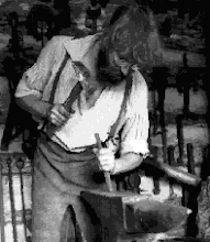
I watched the blacksmith at Stirbridge work 1 x 1 stock on this - pretty much draw to a short point in one heat.
Circa 1830's design, if not earlier. Still effective...
This basic principle is the same that is used for the the original ABANA 'push / pull' small air hammer. I have an early version of this type in my own workshop:
 |
| 50 lb air hammer (light blue) in the corner of the forge area |


No comments:
Post a Comment